


 28 / 100

•
Statement of feasibility – EIL (2017).
•
Technical qualification plan – Peritus International and
DNVGL (2018).
•
Japanese and European pipe mill qualification –
JFE (2018/2019), Europipe (2018/2019).
•
Update of detailed marine survey definition and SOW –
Peritus International (2019).
MEIDP system
The MEIDP project consists of three components: 1) the Middle
East compression station (MECS) in Oman, 2) an offshore
pipeline from Oman to India, and 3) the Gujurat pipeline
receiving terminal (GPRT) in India.
The design average annual throughput of the pipeline
is 10.3 billion m
3
/y, which equates to a peak throughput of
30.96 million m
3
/d, allowing for downtime and maintenance.
The system will be designed with a maximum design pressure
(at the MECS) of 400 barg and a minimum receiving pressure (at
GPRT) of 50 barg. A simple representation of the battery limits is
presented in Figure 2.
Offshore pipeline
The MEIDP has been designed to meet the requirements of
DNVGL-ST-F101. The pipeline’s starting point is at the MECS
located near Ras al Jifan, on Oman’s east coast, and it ends
at the GPRT near Porbandar in the south of India’s Gujurat
state. The pipeline will have a constant internal diameter (ID)
of 610 mm (24 in.) and a wall thickness that varies between
32.9 - 40.5 mm, depending on section and water depth. The
steel grade will be DNVGL SAWL485 FDU – which is an
API5L X70 equivalent. The pipeline route length for the base
case route is 1200 km, and the deviated route avoiding the
Pakistan side of the Oman/Pakistan ECS claim median line is
1300 km. The maximum water depth along the route (base or
deviated) is 3450 m, with more than 85% of the route being
deeper than 2500 m, as illustrated in Figure 3. The estimated
linepipe steel tonnage is between 800 000 - 880 000 t,
depending on the route adopted.
The MEIDP route crosses several geological regimes
(Figure 5). The dominating features of the Oman shelf are
hardgrounds with coral structures covered by a thin blanket
of fine soft sediments, likely to be very soft to soft calcareous
sandy clay/silt. The Oman slope is dominated by complex gully
and channel systems reaching down to the continental rise
where multiple slump deposits are seen. The seabed of the
Oman Abyssal Plain is smooth and featureless, covered by very
soft to soft calcareous clay/silt. The route also crosses multiple
faults at the Owen Fracture Zone (OFZ) and the associated
Dalrymple Horsetail. The pipeline route in the Upper Indus Fan
crosses large channel-levee systems originating from turbidity
mass movements derived from significant historical sediment
inputs of the Indus river.
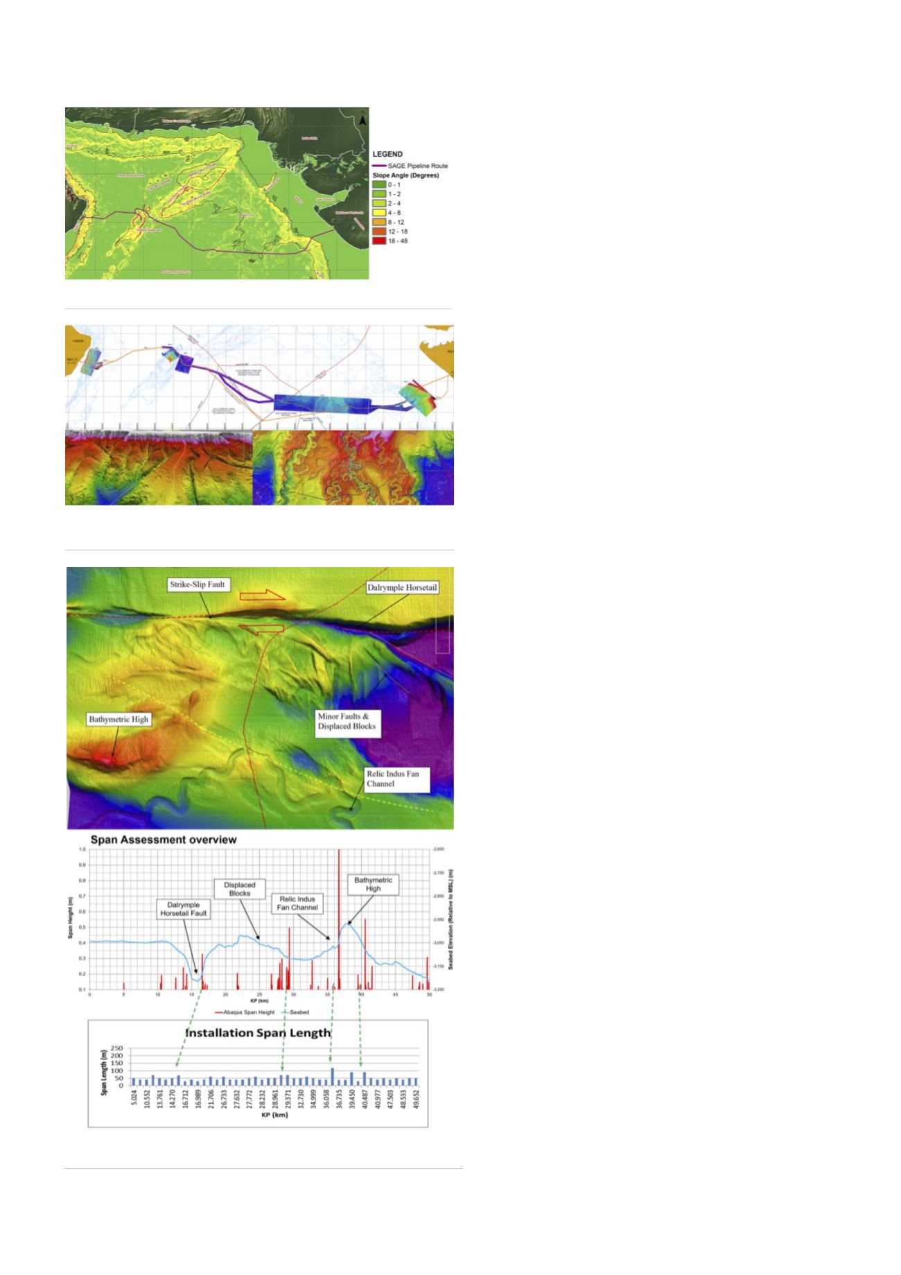
Geohazard challenges
A preliminary geological and geohazard route assessment has
been performed by Fugro. This assessment identified expected
hazards. The larger identified hazards are presented in Table 1
and Figure 4.
Figure 5.
2013 reconnaissance survey (Oman continental slope and
Indus Fan).
Figure 4.
Map of seafloor slope angle and features.
Figure 6.
MEIDP route across Owen Fracture Zone.
26
World Pipelines
/
MARCH 2020