


 100 / 160

March
2017
HYDROCARBON
ENGINEERING
98
Analyser design
Vibrating technology used
In 1981, Sofraser created and patented the first vibrating
viscometer using the vibrating technology at resonance
frequency (Patent N° FR 2 544 496).
3
The active part of the
sensor is a vibrating rod held in oscillation at its resonance
frequency (Figure 1).
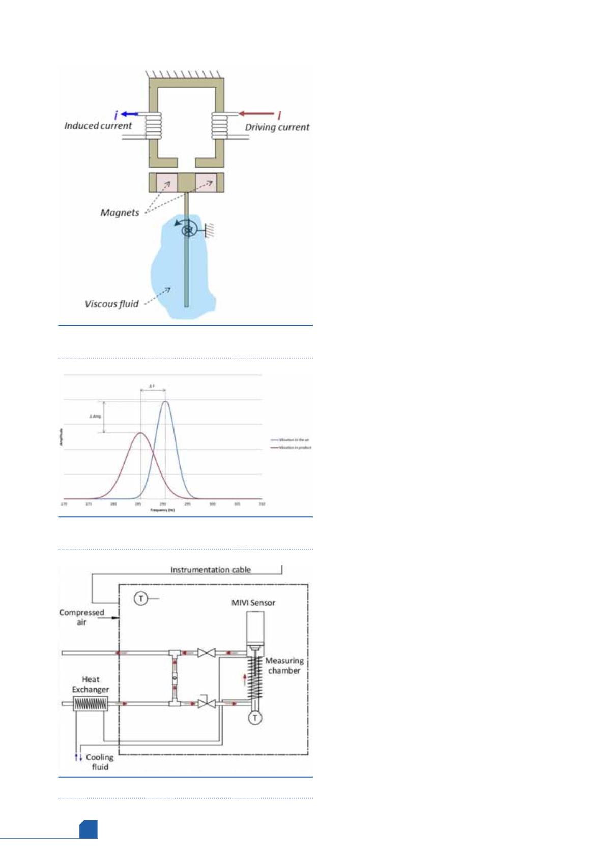
When a rod immersed in a fluid is held in vibration at
resonance frequency, the vibration changes and evolves
depending on the fluid. A variation of the amplitude can
be seen (
Δ
Amp) but also of the resonant frequency (
Δ
F).
Figure 2 shows the amplitude and frequency shift from air
when immersing the vibrating rod in a liquid product.
During calibration, the amplitude of the vibration is
correlated to the viscosity of the product by comparing
the vibration in the air (maximum vibration) and in the
viscous product, thus providing a reliable, repeatable and
continuous viscosity measurement. This principle is
described in patents FR 2 911 188 B1
4
and FR 2 921 726 B1.
5
The amplitude variations correlate to the dynamic
viscosity of the fluid. A relationship
Δ
Amp = f(
η
) was
established in the past, which allows for the measurement
of dynamic viscosity of fluids. The variation of frequency
is made possible by the resonant state at which the
viscometer operates, as opposed to other types of sensor
using a known set frequency to operate. The resonant
frequency depends upon the characteristics of the
oscillator and the medium characteristics (viscosity and
density) in which the rod vibrates. The medium acts as a
buffer, dampening the motion of the rod (and hence, its
frequency). The Sofraser sensor is then able to directly
determine the kinematic viscosity, the dynamic viscosity
and the density by measuring amplitude, frequency and
temperature.
New analyser design and adaptation of
vibrating technology
In order to stabilise the temperature of both product and
sensor, a first heat exchanger is inserted before the
product inlet of the analyser (Figure 3). This first heat
exchanger allows the temperature of the product to be
brought within a few degrees of the reference
temperature. The coolant used in the first heat exchanger
is supplied by a water chiller to allow the coolant
temperature to rest at a few degrees above the reference
temperature.
Once the product exits the first heat exchanger, its
temperature is a few degrees above the reference
temperature. The temperature of the product is
monitored continuously as it exits the heat exchanger. If
the temperature of the product is the same as the
reference temperature (within an acceptable limit) and it
reaches the sensor, the product flows through the
flow-cell and the kinematic viscosity measurement at
reference temperature is made continuously.
If product temperature is too high with regards to the
reference temperature, the product is locked into the
flow-cell (on a bypass loop) and is allowed to cool to the
reference temperature. As the product is only a few
Figure 1.
Principle of the vibrating viscosity sensor at
resonance frequency.
Figure 2.
Frequency and amplitude shift between air and
liquid product.
Figure 3.
New analyser schematic.