


 130 / 160

March
2017
HYDROCARBON
ENGINEERING
128
and machining. At least one rupture disc is tested at
room temperature and two rupture discs are tested
at the rated burst temperature.
The outer dimensions (W x D x H) of the test
block are approximately 600 x 600 x 1000 mm. The
time to heat up the rupture disc is about three to
four days. As such, it takes some time to perform
tests at high pressure and high temperature. It is
important to perform tests for HPRDs and it may not
always be enough to extrapolate test results for
lower burst pressures. All influencing parameters
such as material, material thickness, pressure and
temperature, account for the significant differences
between lower and higher burst pressures.
The detailed test setup (Figure 2) illustrates the
placement of the rupture disc as well as the blank
holder and the threaded flange geometry, alongside
the high pressure stud bolts. Two drains are also
presented; one to set the test pressure and another
to install a measurement system to detect the
pressure directly in front of the rupture disc. The
blank holder is installed above the rupture disc unit.
This component is simultaneously used as a blow off
device to relieve the pressure after the rupture disc
opens. In respect to the expected high pressures, a
robust design is necessary to perform safe tests.
The rupture disc unit is installed using a
customised ‘wafer flange’, which is used as a sealing
to increase the pressure up to the defined burst
pressures. Below the rupture disc, a higher volume is
shown to increase the test volume and to ensure a
reliable opening behaviour.
Another challenge is the manufacturing of the
rupture disc. Rupture discs for high pressures are
usually manufactured using housing and a rupture
disc, which is ‘flat welded’ onto the housing
(Figures 3 and 4).
A typical welded design for a standard high
pressure rupture disc with an indicated welding seam
is shown in Figure 4 and a flat plate is welded onto
the housing in Figure 5. Using the standard version,
the weld seam has an influence on the burst pressure.
This leads to another influencing factor besides
material thickness and dome height, which are used
to adjust the burst pressure. The weld seam is a
function of additional parameters that have to be
considered with respect to the burst pressure and
the life time. In Figure 6, a typical rupture disc failure
is presented where the weld seam of the rupture disc
failed. As a result of this, it is important to test the
rupture disc to prohibit an undefined opening, an
undefined burst pressure, and a shortened lifetime.
Solution
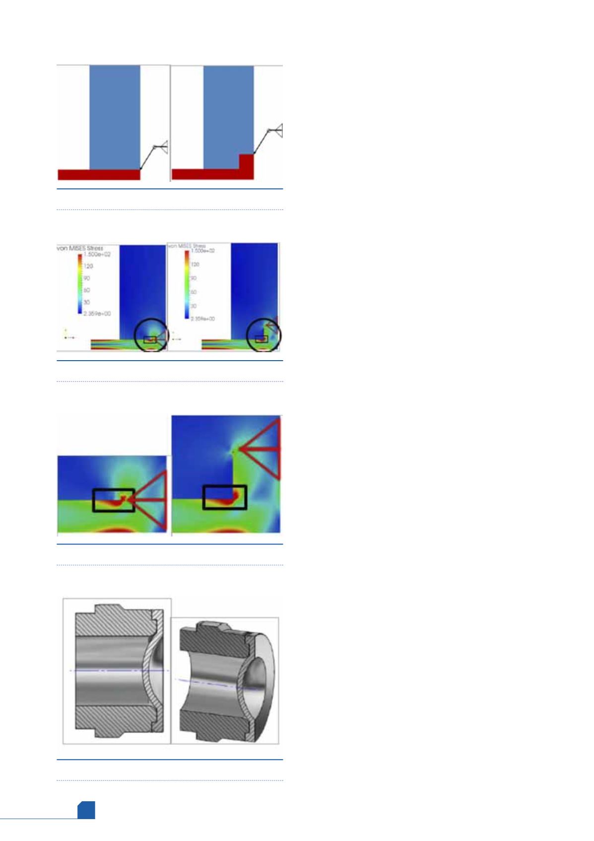
In Figure 7, a schematic model shows the differences
between a standard rupture disc (left) and an
optimised rupture disc (right). A small geometrical
change helps to prevent the welding seam influence
Figure 8.
Rupture disc unit – finite element analysis.
Figure 9.
Rupture disc unit – magnified presentation.
Figure 7.
Rupture disc unit – schematic model.
Figure 10.
Rupture disc unit – longlife version.