


 128 / 160

March
2017
HYDROCARBON
ENGINEERING
126
of the customer. Because of this, the design (Figure 2)
is a ‘show and tell design’. In reality, the nominal size,
the flange connection or the housing is customised
with consideration to the requirements of the
customer.
A HPRD is designed in line with typical high
pressure design standards, using materials for high
pressure applications and considering typical
and/or customised standards in manufacturing of
rupture discs and safety devices. Next to the
standard EN ISO 4126-2, further standards such as
American Society of Mechanical Engineers (ASME)
Section VIII, Div. 1, pressure equipment directive
(PED) 97/23/EG or AD2000-Merkblatt are possible
fundamentals. Depending on the different standards,
different requirements for manufacturing, testing,
documentation, materials, etc. are given. The
following sections of this article are described using
a typical design and typical tests for a HPRD in
general.
5 - 9
Qualification
Tests with high pressures and high temperatures are
quite demanding. Burst tests are usually performed
using a hydraulic press or a vessel, pressurised by
compressed air, nitrogen or hydraulic oil for plug
rupture discs. The qualification requirements to test
a HRPD are much more complex. An experimental
setup has to be designed for reliable, reproducible
and, primarily, safe testing in applying high pressures
(approximately 2500 bar g) and temperatures
(approximately 300˚C).
These tests are executed once, to qualify this
rupture disc to protect LDPE processes. The first
tests were performed at environmental temperature
and with lower burst pressures. In total, 15(+) tests
are required to qualify the experimental test setup.
The burst tests are performed using a medium
consisting of oil and water. At high pressures, it is
important to run the tests without any percentage
of gas. Due to this, the complete experimental test
setup is deaerated. Using a gaseous medium, the
dynamic forces are much higher than using a liquid
as a test medium.
As an experimental setup, a ‘test block’ is used.
The rupture disc (unmounted) will be placed
directly within the test block, jammed below the
blank holder design and fixed using high pressure
bolts. The flange connection at design condition
and the bolts are calculated using ‘AD Merkblätter
B7/B8’ and Deutsche Industrie Norm (DIN) 2505.
10, 11
The test block consists of a block and a blank
holder to install the rupture disc, threaded flanges,
stud bolts and hexagonal nuts to assemble the
experimental setup as well as the rupture disc
assembly. The pressure will be applied using a
connection installed at the side of the test block.
On the opposite side of the test block, another
connection system is installed to detect the pressure
applied on the rupture disc. The blank holder
consists of an inner pipe to relieve the pressure after
the rupture disc has opened. This part is installed
using threaded flanges. On each side, different pipes
are placed to install diverse heating rods to heat up
the test block. Furthermore, loops are installed to
handle the experimental setup. The applied pressure
is produced by a high pressure pump. The fluid is
heated up to 300°C and above. As many as 20 tests
are needed to verify the testing methods; three
rupture disc tests are performed to verify the
rupture disc and the rupture disc assembly. These
tests include the pressure-containing housing, the
carefully adjusted rupture disc and the
manufacturing of the rupture unit, including welding
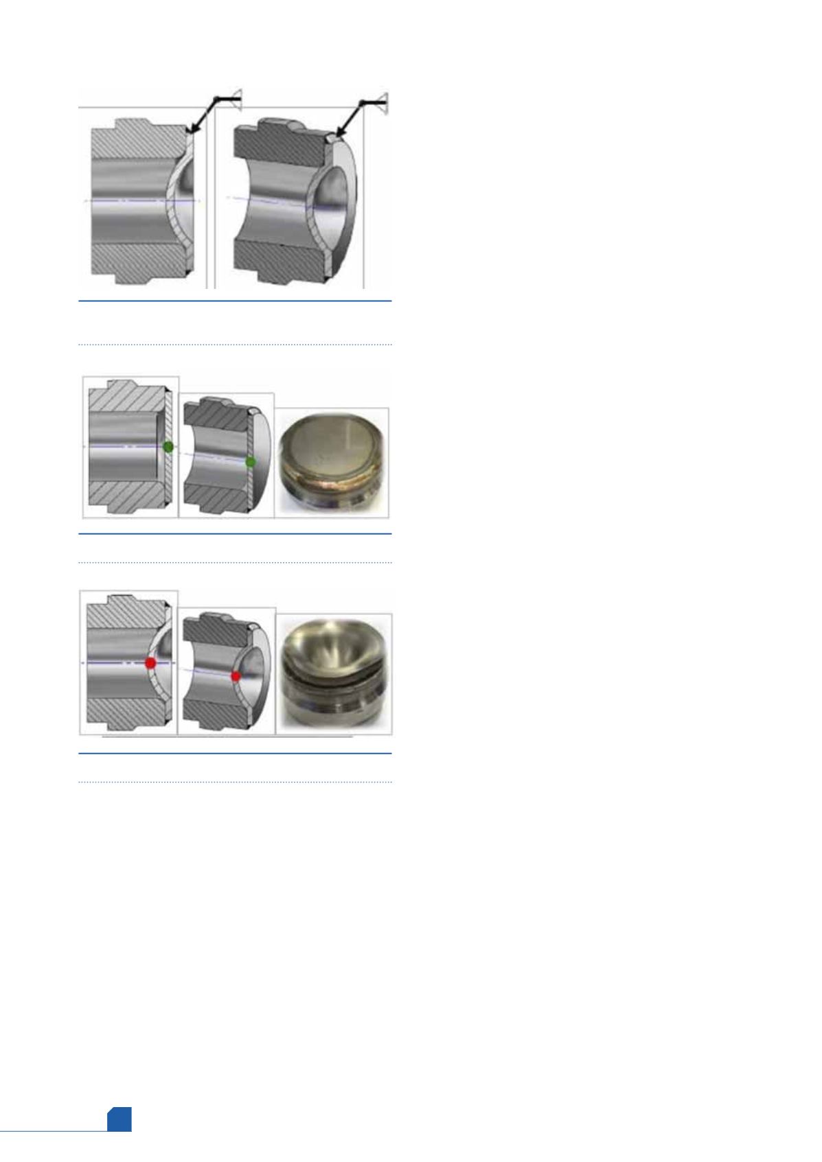
Figure 4.
A typical welded design for a standard high
pressure rupture disc.
Figure 5.
Rupture disc – standard version.
Figure 6.
Rupture disc manufacturing.